Current Approaches
The drawbacks noted in these current approaches are not caused by poor workmanship or substandard materials; they arise from employing designs suited to the south in northern communities.
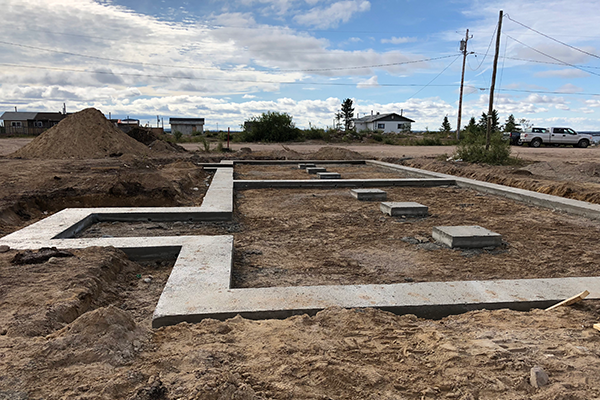
Pony Wall
Homes in the Taiga Shield Ecozone tend to use foundation building techniques adapted from southern precedents. Unless the home is to be built on bedrock, the usual approach is:
-
- dig a shallow rectangular hole
- lay down gravel
- pour a concrete footing
- build “pony walls” about 3 ft high up from the footings
- insulate the pony walls
- build beams on the pony walls, and then joists on the beams
 |
 |
This approach has a number of apparent benefits:
-
- Home builders are familar with this technique.
- The crawl space below the floor can be used for storage.
- Water and sewer lines can be brought into the crawl space.
- HRV (Heat Recovery Ventilation) and other building systems can be located in the crawl space.
- The floor can be insulated from below.
It also has significant drawbacks, which are usually not as apparent:
-
- Working heavy equipment—particularly an excavator—must be available (and in good repair) in the community.
- A skilled heavy equipment operator must also be present.
- Cement must be brought up, gravel and sand must be procured, and concrete must be mixed and poured.
- Insulation needs to be brought in and attached to the pony wall.
- Building systems can be a challenge to access for maintenance and repairs in a crawl space.
- Radon levels (a common problem in the region) are increased because the ground has been disturbed.
- If the building is heated by diesel, any leakage from the tank, piping or furnace accumulates in the crawl space, producing diesel fumes that often leak into the house.
- In spring, when the snow melts (and it often rains), because the ground will not be thawed, water accumulates in the crawl space and contributes to the growth of mold in the crawl space and, sometimes, elsewhere in the building.
- Insulating the pony walls holds the warm, moist air in the crawl space, adding to any mold growth.
- Working heavy equipment—particularly an excavator—must be available (and in good repair) in the community.
The last three of these problems—radon, diesel fumes, and mold—can have devastating effects on people’s health.
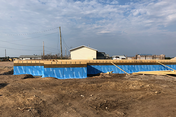
Some newer buildings are starting to use Insulated Concrete Forms (ICFs).
 |
This variant usually reduces heating costs, but still has almost all the same drawbacks of more conventional pony wall systems.
Slab on Grade
Although not as common now as in the recent past, some homes are still built “slab on grade”.
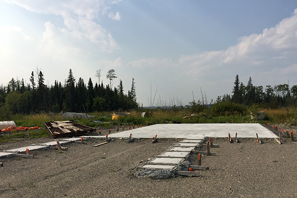 |
This removes many of the problems of the crawl space, but has drawbacks of its own:
-
- Cement is still required, with the problems noted above.
- Insulation is required below the cement to prevent permafrost freeze/thaw and heaving.
- This is a required whether the permafrost is continuous or discontinuous.
- Global warming is resulting in thawing of permafrost, increasing the risk of frost heave and subsidence.
- The floor may be cold.
- Installing and repairing water and sewer lines can be a challenge.
- These lines are usually run below the frost line and then brought up into the building.
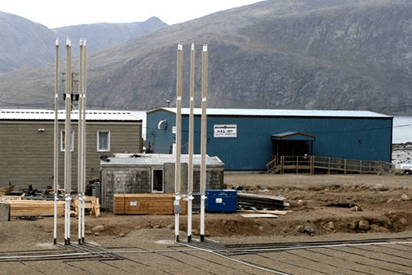
Screw Piles
In recent years, some builders have started to use screw piles instead of concrete footings. These have some advantages, but also have disadvantages:
-
- Screw piles are not designed for use if permafrost (either continuous or discontinuous) is present.
- If boulders are present close underground, the screw piles may not penetrate to the required depth. This can be a problem particularly if building on an esker.
 |
 |
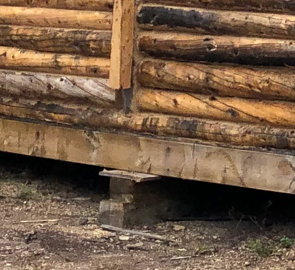
RTM (Ready To Move)
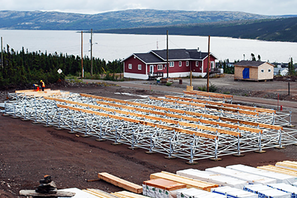
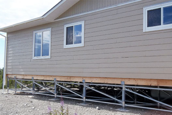
RTM buildings are usually installed on more temporary foundations (although they may remain in place for a long time.
If they are trucked in with a steel undergirding, all that may be needed for a foundation is a packed, level gravel pad and short lengths of pressure-treated 6×6 lumber.
 |
 |
Innovative Approaches
Multipoint
One of the more innovative ways to address foundation problems in the north is Triodetic’s Multipoint Foundation:
 |
 |
This web of aluminum tubing distributes the weight of the building across the entire site.
Thermosyphon
Thermosyphon, Pangnirtung Health Centre
Image source: Holubec, I. (2008). Flat Loop Thermosyphon Foundations in Warm Permafrost. https://www.inf.gov.nt.ca/sites/inf/files/flat_loop_thermosyphon_foundations_in_warm_permafrost.pdf
Thermosyphons use passive heat transfer to keep the permafrost under a building frozen.
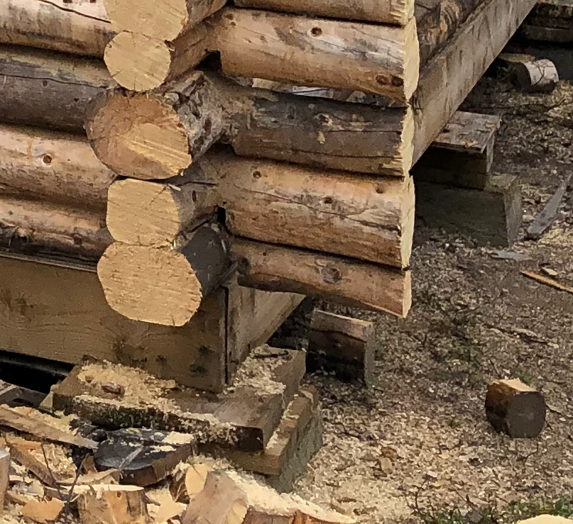
Traditional Foundation Approach
The approach proposed here is based on traditional precedents that have worked in the past in the Taiga Shield Ecozone.
Cabins and outbuildings in the Taiga Shield have traditionally rested on what might seem like only minimal foundations. Some are built directly on the existing ground or bedrock. Sometimes, flat boulders or short logs were spaced out evenly, and beams laid on top of them. (Traditionally, those beams were simply logs. Care was taken to use the largest logs available for these beams, and they were carefully stripped of bark.)
Newer cabins and outbuildings often use short sections of wooden beams or dimensional lumber in place of the boulders or short logs. These are often available as discards from larger commercial building projects.
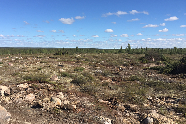
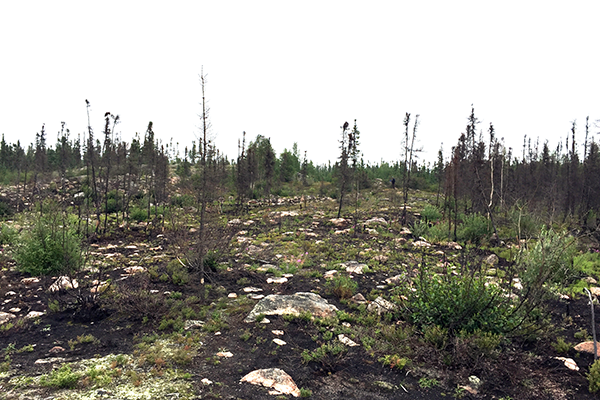
Traditionally, when siting a home or other building, care was taken to avoid muskeg and low-lying areas, and to locate the structure on dry, slightly raised ground or on a flatter section of bedrock. Attention was paid during snow melt and spring run-off to ensure the location where the building was to be built remained dry during this period.
The existing ground surface was not disturbed, although organic matter was often removed where the boulders or short logs were to be located. Because the ground surface had not been disturbed for many years (stretching, in some locations, back to the retreat of glaciers about 7,000 years ago) the ground was almost always already densely packed and very firm.
 |
 |
Because soils in the Taiga Shield have very little organic matter in them, these precautions (stripping the logs of bark, careful attention to drainage patterns, minimal ground disturbance, sometimes a slight elevation above the existing ground using boulders or short logs) resulted in foundations which don’t rot and could last for many years.
These design decisions, while subtle and not always obvious, were crucial.
Taiga Shield Foundation Approach
This approach is derived from the traditional one, with some modern enhancements.
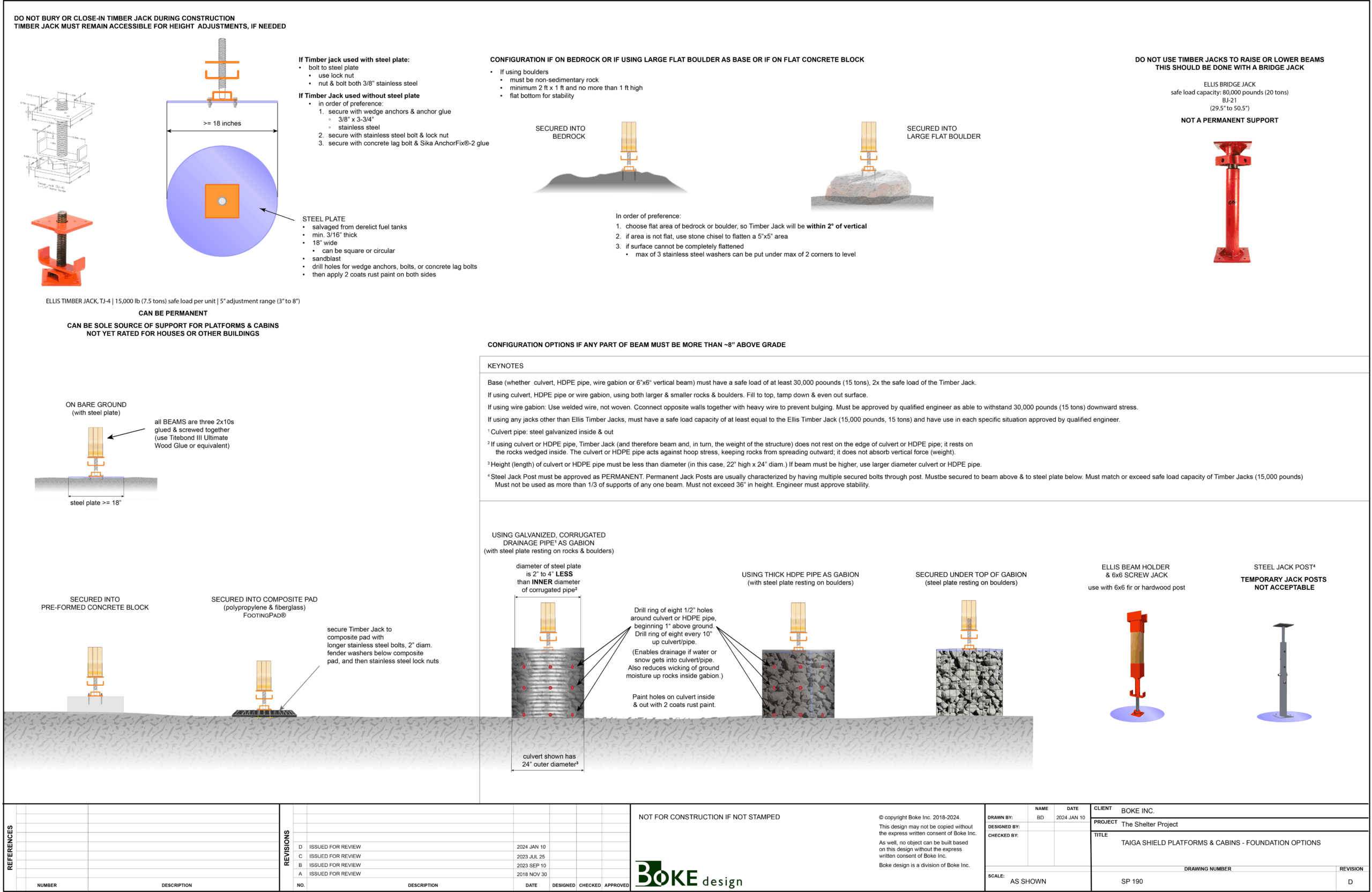
The key addition required are timber jacks.
The timber jack shown here is the TJ-4 Low-Profile Timber Jack, produced by Ellis Manufacturing:
-
- Each one has a lifting capacity of 6,000 lbs (~2.7 tonnes) and a load bearing capacity of 15,000 lbs (~6.8 tonnes).
- It has a vertical adjustment range of 5 inches (~12 cm) and can be adjusted with basic hand tools.
(Ellis Manufacturing also produces a TJ-6, with a load bearing capacity of 30,000 lbs [13.6 tonnes]. This heavier timber jack is not proposed here because, over time, unless it is secured into bedrock, that much weight concentrated on a single point may cause ground surface deformation.)
Each timber jack should be secured to the beam above with either galvanized, heavy-duty nails, deck screws, or lag bolts. They can be made secure to the ground in one of at least five ways:
-
- into bedrock
- into a large, flat boulder
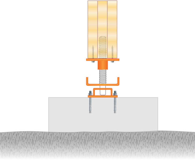
- into a pre-formed concrete block
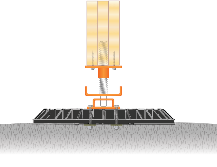
- into a composite footing pad
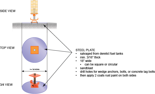
- onto a steel plate, which rests on the ground
1. into bedrock |
2. into boulders |
 |
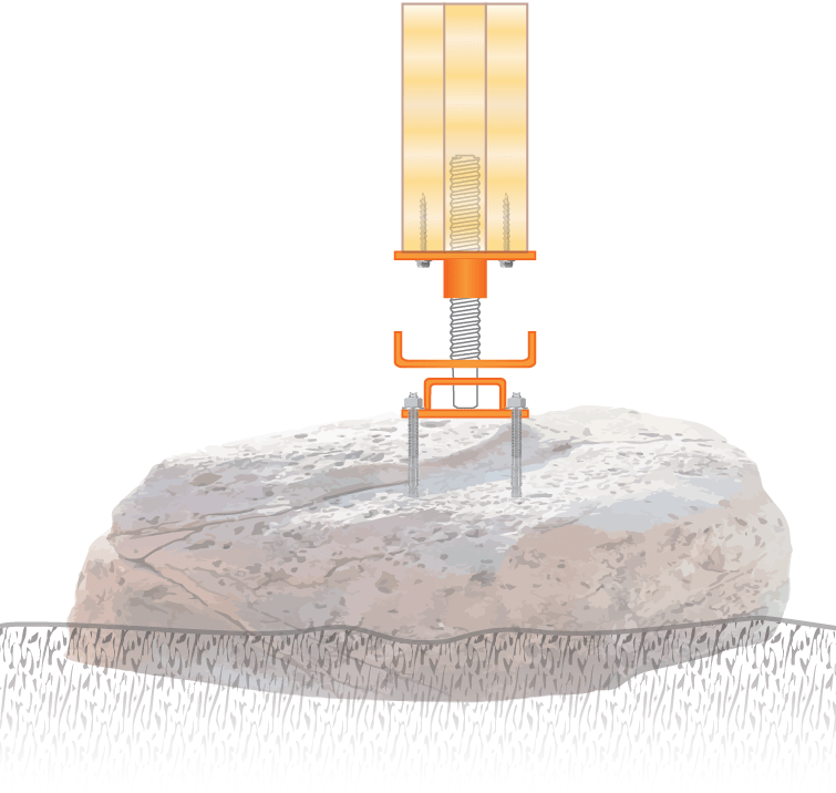 |
3. into a pre-formed concrete block |
4.into a composite footing pad |
 |
 |
5. onto a steel plate, which rests on the ground |
 |
Site conditions, available local materials, and community preferences will guide which of these options—or perhaps another option not considered here—is chosen.

Before global warming began to alter permafrost in the north, timber jacks, with their ability to raise or lower the section of beam directly above them, were largely unnecessary.
Until global warming is brought under control (which will not happen in our lifetime), a method for adjusting the foundation to adapt to fluctuating ground surface heights will be essential.
A few notes:
-
- The spacing between beams, and the spacing of the timber jacks underneath each beam both need to be determined by an engineer with relevant knowledge.
- The weight of the building, the ground’s resistance to deformation, and likely effects of melting permafrost will all need to be taken into consideration.
- Care must be taken to ensure the timber jacks on the periphery of the building are spaced close enough together to easily bear the full weight of the building, as well as any reasonably-forseable additions or enhancements that could come in the future.
- Because this project proposes that the outer walls of buildings be made of double rows of logs, these buildings will be much heavier than a southern building of the same size.
- Further weight from the roof and snow loads will also bear down on this periphery.
- Perhaps the most durable option is to attach the timber jacks directly to bedrock, if it is accessible at the build site.
- Stainless steel wedge anchors, glued with commercial anchoring adhesive into 5″ holes drilled into the bedrock will last for decades.
- indicative glue: Sika AnchorFix®-2
- If the building is ever moved, the achors can be cut off at bedrock-surface level and new anchors used at the new site.
- Stainless steel wedge anchors, glued with commercial anchoring adhesive into 5″ holes drilled into the bedrock will last for decades.
- The timber jack can also be attached to a boulder, if the building is not built on bedrock, and boulders are available.
- The boulders must NOT be made of sedimentary rock, which is prone to breaking when put under stress.
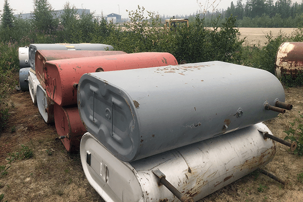
- If the community depends on diesel for heat or power (either currently or in the recent past) there will be plenty of discarded storage tanks.
- If they have had the diesel completely removed, old single-wall “day” tanks that have been discarded because of leaks can be cut up and harvested for steel plates to attach under the timber jacks.
- The spacing between beams, and the spacing of the timber jacks underneath each beam both need to be determined by an engineer with relevant knowledge.
-
- Welding the steel plates to the bottom of the timber jack is feasible, but is not recommended here.
- The timber jack is powder coated, and the steel plate will almost certainly have rust on it. Removing those materials to ensure no weld joint ever fails is more difficult—and perhaps less durable—than stainless steel bolts and lock nuts.
- This arrangement also ensures that, if the building is ever moved, alternative means of anchoring the timber jack can be used, if appropriate.
- The timber jack is powder coated, and the steel plate will almost certainly have rust on it. Removing those materials to ensure no weld joint ever fails is more difficult—and perhaps less durable—than stainless steel bolts and lock nuts.
- Welding the steel plates to the bottom of the timber jack is feasible, but is not recommended here.
- If the building site is accessible by an all-season road (so that weight does not pay a critical role in transportation costs), anchoring the timber jacks to concrete blocks may be the best solution.
-
- Concrete footing pads measuring 18″x 18″ and at least 6″ thick are strongly recommended.
- Thinner concrete pads will be prone to failure when put under pressure.
- Concrete footing pads measuring 18″x 18″ and at least 6″ thick are strongly recommended.
-
- Polypropylene/fibreglass composite footing pads may be the best solution if:
-
- neither derelict steel plate is not available locally,
- suitable boulders are not available locally,
- the building is not going to be built on beddrock, and
- the building site is not accessible by an all-season road (which means transportation costs, calculated by weight, will be high).
- Because these footing pads were not designed as supports for a home or occupied building foundation, testing will be needed before they can be used for homes and buildings that will be occupied.
-
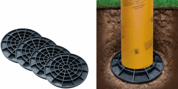
The footing pads shown here are by FootingPad®, and mentioned here as an indicative product, which means substitutes may be acceptable, provided their performance can be determined as equal or superior to the indicative product, and they are accepted as a substitute by the engineer stamping the construction drawings.
The drawings have further notes, including options for sloped and uneven sites.
The approach proposed here has the advantages of:
-
- low cost to try as a prototype
- minimal shipping and installation costs
- can be installed, adjusted and replaced by local people
- can be used to shore up one or more sagging corners of an existing building
- designed for changing permafrost conditions
- is based on precedents that have worked in the past
What is proposed will, no doubt, have drawbacks. Nothing’s perfect and nothing lasts forever. We won’t be able to compare the advantages and drawbacks of this approach to all the others listed above until we have a prototype in place.
It would be best if the first prototype was not a home or large community building. A small non-residential building (such as a storage shed) or a retrofit on a building that has obvious problems (such as the sagging corner on an existing house) would probably the right prototype to start with.
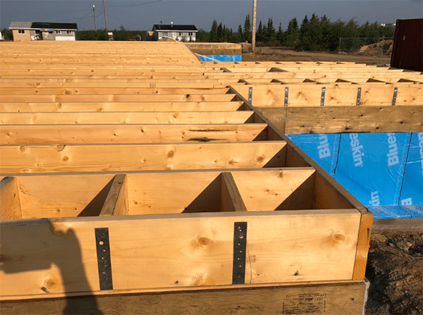
Beam Grid
Ensuring a building rests on a grid of strong, durable beams is an essential requirement for a long building life.
Our design copies the beam-and-joist system common to well-built homes, integrated with the timber jacks to cope with melting permafrost and subsidence.
Beams & Joists on a Pony Wall Foundation
The beams are anchored onto the timber jacks.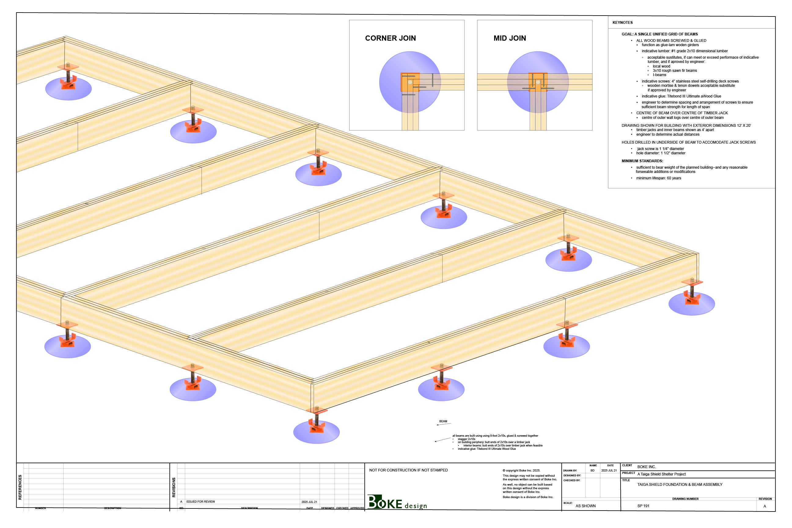 It is essential that an engineer with relevant knowledge review and approve the beam grid design for a specific building on a specific site.
A few notes:
-
- The goal is to create a single, unified grid of beams—somewhat like what the Triodetic’s Multipoint Foundation does with aluminum tubing—but using wood instead of aluminum.
- All wood beams are to be screwed and glued together, functioning as glue-lam girders.
- indicative wood: #1 grade 2×10 dimensional lumber
- acceptable sustitutes, if they can meet or exceed the performace of the indicative
lumber, and if they are approved by engineer:- local wood
- 3×10 rough sawn fir beams
- I-beams
- acceptable sustitutes, if they can meet or exceed the performace of the indicative
- indicative glue: Titebond III Ultimate Wood Glue
- indicative screws: 4” stainless steel self-drilling deck screws
- Glued dowel joints are an acceptable substitute for screws on the outside facing of the beam grid, securing the outer beams to the inner beams, if approved by the engineer.
- indicative wood: #1 grade 2×10 dimensional lumber
- The engineer is to determine spacing and the arrangement of screws to ensure sufficient beam strength for the length of span.
- All wood beams are to be screwed and glued together, functioning as glue-lam girders.
- Centre the beam over the centre of the timber jack.
- Centre the outer wall of logs logs over centre of outer beam.
- The minimum standards for the engineer is to achieve are:
- The grid of beams must be sufficient to bear weight of the planned building—with a reasonable safety factor added—as well as any reasonably-forseeable additions or modifications that may be added to the building in the future.
- Minimum lifespan no less than 60 years.
- The goal is to create a single, unified grid of beams—somewhat like what the Triodetic’s Multipoint Foundation does with aluminum tubing—but using wood instead of aluminum.
Properly designed and constructed—with designs reviewed and stamped by an engineer with relevant knowledge—a foundation based on these designs will be able to adapt to subsidence and should last for many decades.